Node Types
Every node in the Logic Editor belongs to a category. You can find them in the sidebar panel on the left side of the canvas. Drag any node from the sidebar onto the canvas to add it to your graph.
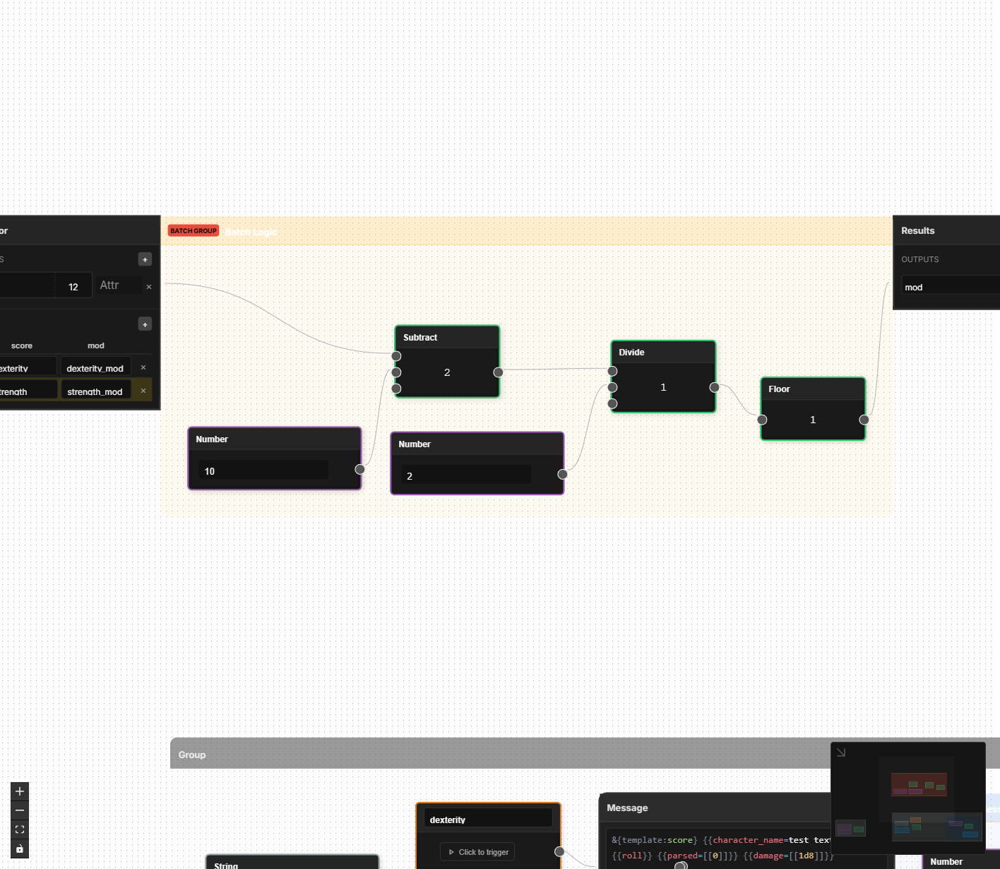
Each node has inputs (on the left side) and outputs (on the right side). You connect an output from one node to an input on another to pass data between them.
Variables
Variable nodes are your starting points. They provide data to the rest of your graph — either by reading values from the character sheet or by supplying a fixed number or text value.
| Node | Inputs | Outputs | What It Does |
|---|---|---|---|
| Attribute | Value (optional) | Value | Reads a character sheet attribute by name. If you connect something to its input, it writes that value back to the attribute instead. This is how calculated results get saved to the sheet. |
| Number | — | Value | Outputs a fixed number that you set (e.g., 10, 2, 20). Use these for constants in your formulas. |
| String | — | Value | Outputs a fixed piece of text that you set. Useful for labels, default values, or text that doesn't change. |
The Attribute node is the bridge between the Logic Editor and your character sheet. Every formula you build will start by reading from attributes and end by writing results back to them.
Read vs. Write mode: The Attribute node changes behavior depending on whether its input is connected. With nothing connected to its input, it reads the attribute value and sends it out its output port. With something connected to its input, it writes the incoming value to that attribute on the character sheet. You can tell which mode it is in by looking at the connections: an Attribute node at the start of a chain (no incoming wire) is reading; one at the end of a chain (wire coming into its input) is writing.
Attributes correspond to the fields you have placed in the Layout Editor. The Attribute node gives you a dropdown of all available attribute names, so you don't have to remember them.
Interaction
Interaction nodes connect your logic to things the player does — clicking buttons and rolling dice.
| Node | Inputs | Outputs | What It Does |
|---|---|---|---|
| Button | — | On Click | Fires a signal when the player clicks a specific button on the sheet. Use this as a trigger to start a chain of logic. You select which button from a dropdown of buttons in your layout. |
| Roll / Message | Trigger, plus one input per field | — | Performs a dice roll or sends a message to chat using a roll template. You write a template string and define fields that get filled in by connected values. |
The Roll / Message node is where your logic meets the dice. You write a message template using Roll20's syntax — for example, &{template:default} {{name=Attack}} {{roll=[[1d20+@{attack_bonus}]]}}. Each {{field}} you reference in the template automatically creates an input on the node that you can connect to other nodes.
If you have used roll templates in Roll20 macros before, the same syntax works here. You can also use inline rolls like [[1d20+5]] inside your template text.
Math
Math nodes perform arithmetic. If you have ever written a formula in a spreadsheet, these will feel familiar.
| Node | Inputs | Outputs | What It Does |
|---|---|---|---|
| Add | Values | Result | Adds all connected values together. You can connect as many inputs as you like — they all get summed. |
| Subtract | A, B, C... | Result | Subtracts in order: A - B - C and so on. The order matters, so inputs are labeled. A new input appears each time you connect one. |
| Multiply | Values | Result | Multiplies all connected values together. Like Add, accepts multiple connections to a single input. |
| Divide | A, B, C... | Result | Divides in order: A / B / C. The order matters. |
| Floor | Value | Result | Rounds a number down to the nearest whole number. 2.9 becomes 2. This is what D&D means by "round down." |
| Ceil | Value | Result | Rounds a number up to the nearest whole number. 2.1 becomes 3. |
| Round | Value | Result | Rounds to the nearest whole number. 2.5 rounds to 3, 2.4 rounds to 2. |
| Abs | Value | Result | Returns the absolute value — strips the negative sign if there is one. -3 becomes 3. |
| Min | Values | Result | Returns the smallest value among all connected inputs. Useful for capping a value (e.g., "HP can't exceed max HP"). |
| Max | Values | Result | Returns the largest value among all connected inputs. Useful for setting floors (e.g., "modifier is at least 0"). |
Add, Multiply, Min, and Max accept any number of connections to the same input. Just drag multiple wires to the "Values" input and they all get processed together.
Subtract and Divide care about order, so they give each connection its own labeled slot (A, B, C...). A new slot appears automatically when you fill the last one.
Logic
Logic nodes let you make decisions — comparing values and choosing different paths based on conditions.
| Node | Inputs | Outputs | What It Does |
|---|---|---|---|
| Compare | A, B | Result | Compares two values using an operator you choose: equals, not equals, greater than, less than, greater or equal, or less or equal. Outputs true or false. |
| Logic Gate | A, B | Result | Combines two true/false values using AND (both must be true), OR (at least one must be true), or XOR (exactly one must be true, not both). You pick the mode from a dropdown on the node. |
| If / Else | Conditions, Values | Per-case outputs | A multi-case conditional switch. Each case has a condition input and one or more value slots. The first case whose condition is truthy wins — its value slots produce output, while all other cases are inactive. If no case matches, the Default slots produce output instead. See details below. |
If / Else Node
The If / Else node is a conditional switch that routes data based on one or more conditions. It replaces the need to chain multiple simple if/then nodes together.
Structure:
Each If / Else node starts with one case and a default. Each case has:
- A When input (left side) — connect a boolean condition here (typically from a Compare or Logic Gate node).
- One or more Then slots — connect the value(s) you want to pass through when this case matches. Each Then slot has a corresponding output handle on the right side.
Below all cases is a Default section with its own value slots and outputs. Default activates when no case condition is truthy.
Adding and managing cases:
- Click Add Case to add more conditions. Cases are evaluated top to bottom — the first truthy condition wins.
- Use the arrow buttons to reorder cases (move up/down).
- Click the × button to remove a case.
- When you have 4 or more cases, a Collapse button appears to hide the case details and save space on the canvas.
Dynamic slots:
Each case (and the default) supports multiple value slots. When you connect to the last empty slot, a new one appears automatically. When you disconnect, trailing empty slots collapse. This lets you route multiple related values through the same conditional — for example, passing both a damage value and a label through the same case.
Inactive case filtering:
Only the matched case's outputs produce values. Outputs from unmatched cases are marked inactive and are automatically filtered out by downstream nodes. This means you can safely connect outputs from multiple cases to the same multi-input node (like Add or Multiply) without getting unwanted values mixed in. Only the winning case's values flow through.
Example: Conditional Proficiency Bonus
Here is a common pattern for applying a proficiency bonus only when a skill is marked as proficient:
- Use a Compare node to check if
athletics_proficiencyequals1. - Connect the result to the If / Else node's first When input.
- On the first case's Then slot, connect your proficiency bonus value.
- On the Default slot, connect a Number node set to
0. - Connect the matching output to the rest of your skill bonus calculation.
The result: proficient characters get the bonus, non-proficient characters get zero.
Example: Multi-Case Damage Type
For a weapon that deals different damage based on a damage type selector:
- Add three cases to the If / Else node.
- Connect a Compare node to each When input, checking
damage_typeagainst"slashing","piercing", and"bludgeoning". - Connect different damage formulas to each case's Then slot.
- Connect a default fallback value to the Default slot.
- Connect the outputs to your damage total calculation — inactive cases are automatically filtered, so only the matching damage formula contributes.
Data
Data nodes handle text manipulation and type conversion.
| Node | Inputs | Outputs | What It Does |
|---|---|---|---|
| Concatenate | A, B, C... | Result | Joins text strings together in order. For example, connecting "Attack: " and a damage value produces "Attack: 8". New inputs appear as you connect them, just like Subtract. |
| Parse Number | String | Number | Converts a text value to a number. If an attribute stores "14" as text, this turns it into the number 14 so you can do math with it. |
| Repeating Section (legacy) | — | Items | Deprecated. This node has been replaced by the Batch Processor's repeating mode, which provides the same functionality plus output targets and built-in aggregation. Existing sheets using this node are automatically migrated. See Repeating Mode. |
Migration notice: If your sheet uses the legacy Repeating Section node, it is automatically migrated to a Batch Processor in repeating mode when you open the sheet. No manual action is needed. The migrated batch processor preserves your section name and creates equivalent input/output slots.
Groups
Group nodes help you organize complex graphs and handle repetitive patterns efficiently.
| Node | Inputs | Outputs | What It Does |
|---|---|---|---|
| Logic Group | — | — | A visual container you can place around a set of nodes to keep them organized. You can name it, color it, and collapse it. Has no effect on calculations — purely organizational. |
| Batch Processor | Varies | Varies | Processes the same formula across multiple data points at once. Supports two modes: manual (fixed table of attribute mappings, e.g., six ability scores) and repeating (auto-discovers rows from a repeating section in your layout). Repeating mode adds output targets (row, running, aggregation) and built-in aggregation functions (SUM, COUNT, MIN, MAX, AVG). See Groups and Batches for a full walkthrough. |
Batch Processors are one of the most powerful features in the Logic Editor. If you find yourself building the same chain of nodes more than twice, a batch node will save you significant time and keep your graph clean.
Custom
For advanced users who need capabilities beyond the built-in nodes.
| Node | Inputs | Outputs | What It Does |
|---|---|---|---|
| Script | Input | Output | Runs a custom JavaScript function. The connected input value is available inside the script, and whatever you return becomes the output. This is an advanced feature — you will need some familiarity with JavaScript to use it. |
The Script node is an escape hatch for edge cases. If you find yourself reaching for it frequently, check whether a combination of built-in nodes can do the job first — built-in nodes are easier to maintain and less error-prone.